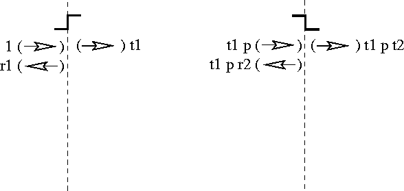
Figure 7: A unit left-incident current
Let us now use our diagrams to compute the scattering amplitudes for the potential of Figure 1. We begin with an incoming wave from the source carrying a unit current, as expressed in Figure 7. This diagram represents the wave function a(x), which is zero in Regions (c) and (t), and, as such, violates the boundary conditions at x=0.

Figure 7: A unit left-incident current
As we have learned, to satisfy the boundary conditions at x=0, we
must include both a transmitted and reflected current, with factors
arranged to satisfy the boundary conditions in the presence
of a unit incoming current. These are precisely the same conditions
we impose when computing scattering from an upward step as in the
``Notes on Scattering Theory.'' Including reflected and transmitted
waves, ![]() and
and ![]() , with the same
prefactors
, with the same
prefactors ![]() and
and ![]() as we found for scattering from a
single upward step,
as we found for scattering from a
single upward step,
will therefore satisfy the boundary conditions at x=0. The
diagrammatic representation of the present stage in our solution to
the TISE appears in Figure 8. Here, the factors ![]() and
and ![]() appearing next to the reflected and transmitted beams are
multiplicative factors. As we will see in Section 3.4,
this determines the appropriate quantum amplitudes for the fundamental
events of reflecting and transmitting across the first step.
appearing next to the reflected and transmitted beams are
multiplicative factors. As we will see in Section 3.4,
this determines the appropriate quantum amplitudes for the fundamental
events of reflecting and transmitting across the first step.

Figure 8: Satisfying the boundary conditions at x=0
The wave function diagrammed in Figure 8 has been
designed to satisfy the boundary condition at x=0 but still
represents a zero wave function in Region (t). The present solution now
violates the boundary condition at x=a. To match this boundary
condition, we follow a procedure similar to that in the previous
paragraph. However, as our standardized form for scattering
amplitudes is based upon current carrying functions centered at the point of
matching boundary conditions, x=a in this case, it is best to first
use (9)
to express our solution in Region (c) in a form centered at x=a.
This results in the function ![]() as indicated in
Figure 9. As we will see in Section 3.4,
this determines the appropriate quantum amplitude for the fundamental
event of propagating across the barrier.
as indicated in
Figure 9. As we will see in Section 3.4,
this determines the appropriate quantum amplitude for the fundamental
event of propagating across the barrier.

Figure 9: Propagating the solution to test boundary conditions at x=a
Now we face the standard scatting
boundary condition problem for a downward step in potential, except
that rather than a unit incoming current, the
incoming current carries a factor ![]() . We know
that the solution
. We know
that the solution
![]()
satisfies these boundary conditions
when ![]() and
and ![]() are the usual scattering amplitudes from a
downward step,
are the usual scattering amplitudes from a
downward step,
Because the TISE is linear, we may multiply this solution to the TISE
by any constant factor and still satisfy the boundary conditions at x=a. To
match our incoming wave ![]() , the factor which we should use
is clearly
, the factor which we should use
is clearly ![]() . Doing this then generates the waves
. Doing this then generates the waves ![]() and
and ![]() as diagrammed in Figure 10.
as diagrammed in Figure 10.

Figure 10: Satisfying the boundary conditions at x=a
As we will see in Section 3.4, this determines the appropriate quantum amplitudes for the fundamental events of reflecting and transmitting from the second step.
The wave function diagrammed in Figure 10 satisfies the
boundary conditions at x=a; however, the new reflected current in
Region (c) designed to satisfy the boundary condition at x=a now
violates the boundary condition at x=0. To match this boundary
condition, it is most convenient to use the identity (10)
to re-express this solution in terms of a wave centered at x=0,
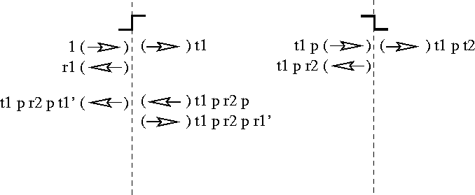
resulting in ![]() , as indicated in Figure
11. This now brings a new uncompensated current to the
boundary conditions which previously had been in perfect balance at
x=0. Because the TISE is linear, to
satisfy the boundary condition at x=0 we need only add the reflected
and transmitted waves corresponding to the new current
, as indicated in Figure
11. This now brings a new uncompensated current to the
boundary conditions which previously had been in perfect balance at
x=0. Because the TISE is linear, to
satisfy the boundary condition at x=0 we need only add the reflected
and transmitted waves corresponding to the new current ![]() . This new current now approaches a downward step
from the right. As shown in Section 3.2.1, the quantum
amplitudes
. This new current now approaches a downward step
from the right. As shown in Section 3.2.1, the quantum
amplitudes ![]() for this are the same as those for approaching
the mirror image from the right,
for this are the same as those for approaching
the mirror image from the right,
Making the appropriate adjustment for the fact that the incoming wave
carried the factor ![]() instead of 1, the reflected and
transmitted parts needed to balance the boundary conditions at x=0
are
instead of 1, the reflected and
transmitted parts needed to balance the boundary conditions at x=0
are ![]() and
and ![]() ,
respectively. This ultimately determines the quantum amplitudes for
reflection and transmission when approaching the first step from
inside the barrier.
,
respectively. This ultimately determines the quantum amplitudes for
reflection and transmission when approaching the first step from
inside the barrier.
These contributions are included in Figure 11. We now have two contributions to the final reflected current. Note that the presence of two forward arrows in Region (c) and two backward arrows in Region (s) (representing the functions c(x) and b(x) respectively) means that these terms should be added in producing the total wave represented by the diagram.

Figure 11: Propagating back to x=0 and re-satisfying the boundary conditions
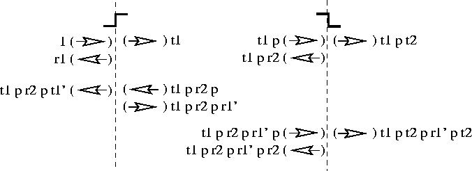
Having adjusted the boundary condition at x=0, we have once again disturbed the boundary condition at x=a. Figure 12 shows the result of propagating this disturbance to the other side of the barrier and adjusting the boundary condition at x=a. The result is a second contribution to the final transmitted current and another term which will then require adjustment of the boundary condition at x=0.

Figure 12: Propagating back to x=a and re-satisfying the boundary conditions
We may continue this process, alternately satisfying the boundary conditions at x=0 and at x=a. At each stage in the process, some current leaks out of Region (c) so that the violation of the boundary condition at x=0 or x=a gets smaller and smaller. Continuing the processes ad infinitum eventually leads to a solution which satisfies all boundary conditions, and we will have built up a solution to the TISE with a proper unit left-incident current and no returning current from the far side of the source. The total of the factors multiplying the reflected current b(x) and the final transmitted current g(x) will then be quantum amplitudes for reflection R(k) and transmission T(k) from the entire barrier. As we see from Figure 12, these amplitudes are therefore
As we shall see in the next section, the Feynman formulation gives us an organized, extremely efficient short-hand for generating these factors.